Balanced Pressure Thermostatic Steam Traps are equipped with a capsule element, which controls the discharge of condensate depending on the temperature. The capsule contains a special liquid, whose saturation temperature at a given pressure is always lower than that of the water. It ensures a very accurate functioning of the steam trap and is self-adjusting.
Series D MIYAWAKI steam traps can be delivered with 3 different capsule types:
|
The discharge characteristic follows the saturation curve independent from pressure changes and the condensate load.
Operating principle
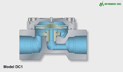
Model DC1
| Model | Available Sizes | Available Connections | Maximum Operating Pressure MPa (psig) | Maximum Operating Temperature °C (°F) | Body and Cover Material | Download |
| DL1 | 1/2″-1″ | Screwed Rc & NPT | 2,1 (305) | 220 (428) | Stainless Steel |
|
| DF1 | 1/2″ – 1″ | Screwed Rc & NPTSocket weld JIS, ASME, DINFlanged JIS, ASME, DIN | 2,1 (305) | 235 (455) | Forged Steel | (138KB) |
| DV1 with bypass | 1/2″ – 3/4″ | Screwed Rc & NPT | 1,0 (145) | 184 (363) | Stainless Steel | |
| DC1 | 1/2″ – 1″ | Screwed Rc, NPT | 2,1 (305) | 220 (428) | Stainless Steel | |
| DC2 & DC2R | 1/2″ male x 1/2″ female | Screwed Rc, NPT | 1,6 (230) | 220 (428) | Stainless Steel | |
| DX | 38 mm | Tri-Clamp | 0,5 (73) | 160 (320) | Stainless Steel |
Features
|
Suitable for:
| Light to medium condensate loads: steam tracing, steam main drips, small heat exchangers, unit heaters, steam heating coils and many other applications in the petrochemical, chemical, textile, food, pharmaceutical and other industries. |
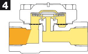
Operating principle:
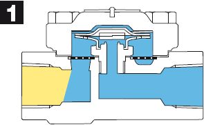
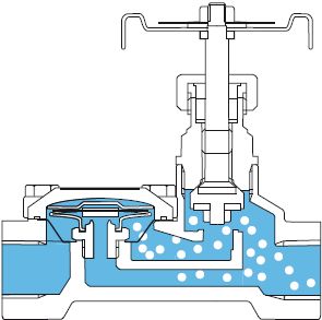
Upon start-up in the presence of cold condensate, the capsule element is contracted and the valve plate has moved away from the seat. The wide open valve discharges condensate and air rapidly.
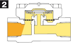
As the temperature inside the trap increases, the capsule element will start to expand, moving the valve plate toward the seat.
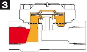
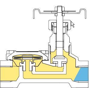
Just before the condensate reaches saturation temperature, the valve plate will close the seat completely. Steam can not enter the trap, ensuring zero steam loss.
As the temperature inside the trap decreases, the capsule element moves away from the seat and the condensate will be discharged. During normal operation steps 3 and 4 will repeat continuously.
Operating principle of DV1 when using the bypass valve:
When the handle is turned in the direction indicated by the BLOW arrow on the nameplate (counterclockwise), the bypass valve will open, a bypass circuit will be formed inside the trap, and a large volume of air and condensate can be discharged quickly. Scale that has accumulated in the screen can also be blown out.
When the bypass valve is closed, the type DV1 will operate as a normal steam trap (see above operating principle).